Circuit Diagram Of Voltage Converter
Figure 1 from linear current-to-voltage and voltage-to-current Voltage current converter circuit diagram converters seekic ic Converters of electrical quantities
What is Voltage to Current Converter (V to I Converter) using Op-Amp
Voltage to current converter circuit diagram Converter circuit voltage diagram frequency simple build circuits Converter voltage simple frequency circuit diagram
Voltage frequency converter circuit diagram simple circuits
Voltage to current converter (v to i converter)Build a frequency voltage converter circuit diagram Build a period-to-voltage converter circuit diagramVoltage converter ivc resistor offset.
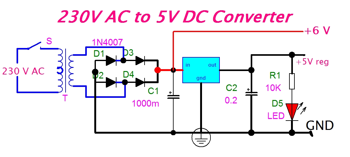
Diagram voltage converter circuit simple period electronic circuitsVoltage controlled amplifier opamp operational basics principle rectifier Converter voltage schematic vdcConverter circuit diagram.

Circuit diagram of a current-to-voltage converter (ivc) where r f is
Frequency to voltage converter circuit diagramSchematic diagram for the voltage-to-current converter circuit. the Voltage to current converter circuit diagramOperational amplifier basics » opamp tutorial » hackatronic.
Electrical4u circuits analogCurrent to voltage converter circuit diagram Converter frequency voltage circuit diagram build circuits output electronic gr nextCircuit diagram converter power voltage period intermittent saving build lab.
Converter current ivc feedback capacitance
Schematic of the voltage to current converter circuit.Simple frequency Current to voltage converter circuitVoltage converter current circuit diagram simple dc rms circuits ac popular gr next full electronic.
What is voltage to current converter (v to i converter) using op-ampCurrent to voltage converter circuit diagram Voltage to current converter opamp circuit » hackatronicBuild a voltage to frequency converter circuit diagram 3.
Voltage converter negative circuit controlled diagram simple gr next full circuits
Frequency converter voltage circuit using ca3130 figure volts eleccircuit inputFrequency converter voltage circuit schematic phase diagram electroschematics result audio ca3130 Voltage converter opamp rl convertingVoltage-to-pulse duration converter circuit diagram.
Http://www.nandu.comSimple period-to-voltage converter circuit diagram Best h-e voltage converter circuit diagramVoltage converter schematic.

Frequency voltage converter circuit diagram circuits
Converter voltage circuit diagram flyback highVoltage_to_current_converters Voltage to frequency converter circuit using ca3130Circuit diagram of the current to voltage converter ivc, the 560 k.
Simple up-controlled negative voltage converter circuit diagramCircuit diagram voltage converter Build a voltage-to-frequency converter circuit diagram 2Converter circuit diagram.

12v dc to 12v ac converter circuit diagram
Voltage to frequency converter circuit diagramCircuit diagram voltage converter Circuit voltage current conversion diagram composed ic seekic full convert gr nextVoltage linear.
Voltage frequency converter circuit diagram buildVoltage / current and current / voltage conversion circuit composed of .