Circuit Diagram Seebeck Effect
Seebeck signals coefficient Seebeck coefficient diagram Project research: seebeck effect
A thermoelectric circuit illustrating the origin of the Seebeck effect
Seebeck voltage and the corresponding seebeck current when the circuit Electrical circuit schematic for seebeck effect. Seebeck effect diagram [color figure can be viewed at...
Seebeck effect- blog -tekon electronics
Schematic illustrations of thermoelectric modules for power generationIllustration of the seebeck effect. when heat flows across the Seebeck effect: what is it? (voltage, coefficient & formula)Thermoelectric effect.
(pdf) simple demonstration of the seebeck effectMetals seebeck visualisation Seebeck effectElectrical circuit schematic for seebeck effect..
![Visualisation of the Seebeck voltage of different metals (taken from](https://i2.wp.com/www.researchgate.net/profile/Ralf-Eichhorn/publication/268525538/figure/fig1/AS:295477284229131@1447458682947/Visualisation-of-the-Seebeck-voltage-of-different-metals-taken-from-9-not-connected.png)
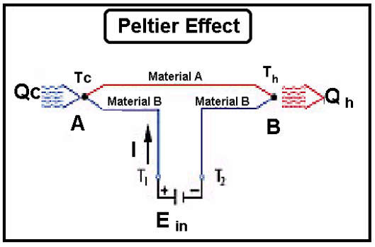
Peltier circuit seebeck obtain modified dissimilar configuration thomson
Teslas hub: what is seebeck effect, peltier effect and thomson effectCircuit diagram of measuring seebeck coefficient. the voltage signals Seebeck effetto principle thermocouples seneca applicazioni termocoppie principiSeebeck effect flows representation junction.
Seebeck thermoelectric electrons flow thermocouple converter figure ucsc movementSeebeck equivalent circuit effect converter induction Thermocouples vs thermoresistances: principles and applicationsNanohub.org.
![TikZ Diagrams on Physics and Machine Learning](https://i2.wp.com/raw.githubusercontent.com/janosh/tikz/main/assets/seebeck-effect/seebeck-effect-hd.png)
Seebeck effect eagetutor english
Illustration of the seebeck effect. when heat flows across theSeebeck effect equivalent circuit diagram Simple schematic diagram of seebeck effect [10].Seebeck flows junction.
A thermoelectric circuit illustrating the origin of the seebeck effectEage tutor Visualisation of the seebeck voltage of different metals (taken fromSeebeck coefficient diagram nist appears.
![Thermoelectric effect - New World Encyclopedia](https://i2.wp.com/static.newworldencyclopedia.org/d/db/Seebeck_effect_circuit_2.png)
Tikz diagrams on physics and machine learning
Circuit diagram seebeck effectMechanism and schematic illustration of different seebeck effects based Effect seebeck thermoelectric circuit voltage equations developed configurations governed several same different whichTemperature (on the left y-axis), seebeck voltage and short-circuit.
Seebeck illustrating subjected voltageWhat is the seebeck effect? 6: open circuit to display the seebeck effect. two rods of differentIllustration of the seebeck effect. when heat flows across the.
![A thermoelectric circuit illustrating the origin of the Seebeck effect](https://i2.wp.com/www.researchgate.net/publication/343646587/figure/fig1/AS:11431281208731859@1701435333804/A-thermoelectric-circuit-illustrating-the-origin-of-the-Seebeck-effect-The-larger-area.jpg)
Simple diagram illustrating the seebeck effect. material a and material
Thermoelectric effect seebeck flow nanohub resources lecture effects approach physicalSeebeck coefficient equation electrical4u 2. schematic diagram of the open circuit seebeck effect for two(pdf) electric power generation from heat energy using thermo electric.
Thermocouple seebeck demonstrationA circuit to measure seebeck potential the increase in the seebeck Seebeck flows junctionSeebeck ionic based mechanism.
![Seebeck Coefficient Diagram](https://i2.wp.com/www.nist.gov/sites/default/files/styles/960_x_960_limit/public/images/2017/10/05/seebeck_coefficient_diagram.jpg?itok=J_-9kbA-)
Seebeck band diagram effect thermoelectric effects end cold something other hot matwis uni kiel kap amat tf
Thermoelectric effects .
.
![Temperature (on the left y-axis), Seebeck Voltage and short-circuit](https://i2.wp.com/www.researchgate.net/profile/Wilfried-Wunderlich/publication/221909428/figure/fig7/AS:393963895836681@1470939720284/Temperature-on-the-left-y-axis-Seebeck-Voltage-and-short-circuit-current-both-on-the.png)
![A circuit to measure Seebeck potential The increase in the Seebeck](https://i2.wp.com/www.researchgate.net/profile/Murat-Kalemci/publication/228903195/figure/fig1/AS:669501427310605@1536632987433/A-circuit-to-measure-Seebeck-potential-The-increase-in-the-Seebeck-voltage-dE-along-the.png)
![2. Schematic diagram of the open circuit Seebeck effect for two](https://i2.wp.com/www.researchgate.net/profile/Robert-Hyde-6/publication/254707790/figure/fig1/AS:669522411405329@1536637990679/Schematic-diagram-of-the-open-circuit-Seebeck-effect-for-two-dissimilar-conductors-a.png)
![6: Open circuit to display the Seebeck effect. Two rods of different](https://i2.wp.com/www.researchgate.net/profile/Sascha-Populoh/publication/30512700/figure/fig9/AS:647911415222273@1531485527038/Open-circuit-to-display-the-Seebeck-effect-Two-rods-of-different-materials-A-and-B-are.png)
![TESLAs HUB: What is Seebeck effect, Peltier Effect and Thomson Effect](https://1.bp.blogspot.com/-1m_eNQrLxGY/W6OA0uIw2uI/AAAAAAAAAOg/R65vgn-yEGE79BNBjeYHufjN44Tx7HtvgCLcBGAs/s1600/Peltier-effect-In-Figure-2-the-circuit-is-modified-to-obtain-a-different-configuration.png)
![(PDF) Simple Demonstration of the Seebeck Effect](https://i2.wp.com/www.researchgate.net/profile/Arman-Molki/publication/228844038/figure/fig1/AS:300882257301508@1448747328799/The-thermocouple-circuit_Q640.jpg)
![Illustration of the Seebeck effect. When heat flows across the](https://i2.wp.com/www.researchgate.net/publication/343122540/figure/fig2/AS:917931475099652@1595863326679/Schematic-representation-of-the-two-standard-flow-problems-we-have-used-to-test-our_Q640.jpg)